
Background
To systematically validate the environmental adaptability and reliability of automotive electronic products, leading automotive manufacturers including Audi, BMW, Daimler, Porsche and Volkswagen jointly developed the VW 80000 test standard. Based on the full range of electrical environments that automotive electronics may encounter throughout the vehicle lifecycle, the standard clearly specifies the test items, test methods and acceptance requirements for the electrical performance of automotive electronic components, and serves as the universally accepted basis for OEMs in evaluating component electrical reliability. In China, vehicle manufacturers currently perform electrical performance testing primarily in accordance with GB/T 28046.2. As the automotive industry continues to develop rapidly, domestic OEMs are also aligning their technical requirements with international levels: Geely, BAIC and SAIC, among others, have adopted selected test methods from VW 80000 for supplementary verification of components in line with their own product requirements. The interior space of a vehicle is limited and the variety of on-board electronic products is large, making the in-vehicle electrical environment highly complex. The normal operation or any fault of an automotive electronic product — such as those occurring at engine start-up or shutdown, or a short circuit — may affect the vehicle’s electrical networks and surrounding products. Throughout their entire service life, automotive electronic products are continuously exposed to abnormal electrical conditions, including sustained or transient overvoltage and overcurrent, micro-pulses, supply interruptions and short circuits. Consequently, systematic electrical performance verification of automotive electronic products is a critical step in ensuring vehicle electrical safety and improving component reliability.
1. Standard History and OEM Adoption Background
Consolidation of German OEM specifications. VW 80000 evolved from LV 124, an early joint supply specification among German vehicle manufacturers. Audi, BMW, Daimler, Porsche and Volkswagen jointly revised it over long-term vehicle validation practice in order to unify the electrical reliability verification criteria across all brands within the group, avoiding the need to define duplicate validation rules for the same component under different brands.
Continuously tightened as vehicle E/E architecture complexity increased. In early vehicles the electrical load was relatively simple, and test items covered only basic overvoltage, short circuit and insulation. As the number of ECUs increased and DC-DC converters and high-speed bus systems were fitted in large volumes, OEMs progressively added test items such as superimposed AC voltage, micro-pulses, slow voltage fall and rise, short interruptions and ground offset. Acceptance criteria likewise tightened from “whether the function fails” to “whether temporary functional degradation is acceptable” and “whether the reset time meets specification.”
From corporate standard to industry-wide common language. The standard was originally an internal requirement imposed by OEMs on their suppliers. As the German automotive supply chain globalised, its verification methods were widely referenced by component manufacturers, testing laboratories and OEM procurement technical specifications, becoming the electrical performance “entry ticket” to the German vehicle supply chain. For suppliers, passing VW 80000 often means simultaneously satisfying the electrical reliability requirements of several OEMs.
Positioning relative to ISO 16750-2 and GB/T 28046.2. VW 80000 adopts an installation-position-oriented grouping strategy, assigning severity levels by mounting location such as the engine compartment, passenger compartment and exterior components, and superimposes extreme conditions such as Load Dump and cranking pulses over the full temperature range. ISO 16750-2 and its identically adopted national equivalent GB/T 28046.2 instead follow a general-scenario-oriented broad coverage approach. Consequently, passing the Chinese national standard does not automatically satisfy German OEM requirements; both must be executed separately according to the customer-specified standard.
Adoption by domestic OEMs. As the automotive industry developed rapidly, Geely, BAIC, SAIC and other domestic vehicle manufacturers also referenced selected test methods and technical criteria from VW 80000 when formulating their own corporate standards, combining them with GB/T 28046.2 to form a verification system that satisfies both the national standard and international practice, thereby raising the overall electrical reliability level of domestic component enterprises.
2. Purpose of Testing
The core purpose of VW 80000 electrical performance testing is to reproduce, in a controlled manner, the various abnormal electrical conditions a vehicle may encounter before series production, so as to verify component withstand capability and functional stability. Specific objectives include:
Early exposure of design defects. Reveal design flaws in the power supply chain, protection circuits and software control strategies during the development and prototype phases, preventing defects from reaching end users in series-produced vehicles.
Functional safety and reliability confirmation. Confirm that component functional performance under overvoltage, undervoltage, interruption and short-circuit conditions complies with the standard acceptance criteria, safeguarding vehicle electrical safety and the availability of key functions.
Supplier qualification gate. Satisfy OEM supplier technical agreement requirements as a mandatory verification item for entering the vehicle supply chain and securing volume nomination, and serve as a basis for OEM audits and annual quality assessments.
Design optimisation input. Identify weak links in circuit architecture and component selection through the distribution of passed and failed items, providing clear direction for the next design iteration and avoiding cost waste from over-design.
Risk and responsibility clarification. Provide objective, traceable test data to support technical root-cause attribution of subsequent batch quality issues, establishing a consistent technical baseline across design validation, series-production release and after-sales traceability.
3. Main Test Items
Under the VW 80000 standard, electrical performance testing for automotive electronics comprises 22 test items, E-01 through E-22:
- E-01 Sustained Overvoltage. Simulates extreme conditions where the supply voltage remains above the normal operating range for an extended period, evaluating the insulation withstand capability and functional stability of the component under continuous overvoltage.
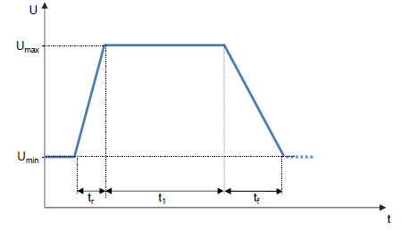
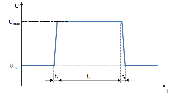 2. E-02 Transient Overvoltage. Simulates transient overvoltage occurring in the electrical system under conditions such as switching off a load or rapid engine speed change (tip-in), evaluating the component’s immunity to short-duration high-voltage surges.
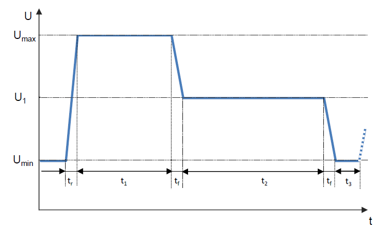 3.E-03 Transient Undervoltage. Simulates undervoltage produced by a momentary drop in supply voltage when a high-power load is connected, evaluating the component’s function retention and recovery capability during voltage dips.
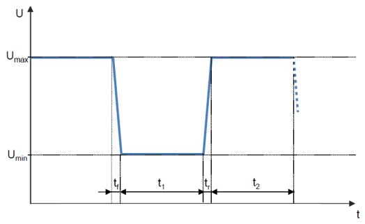
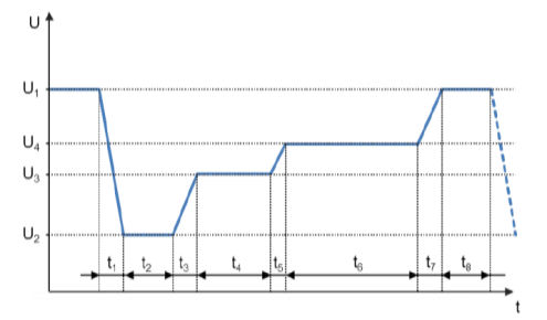 4.E-04 Jumpstart. Simulates jump-starting the vehicle with an external power source (such as rescue battery connection), evaluating the behaviour of the component during voltage step changes.
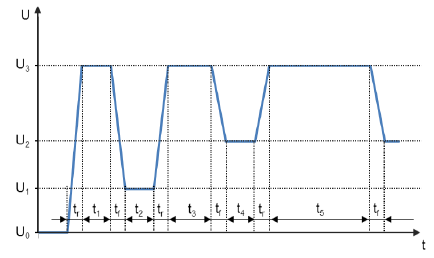 5.E-05 Load Dump. Simulates the high-energy overvoltage pulse generated when the generator suddenly unloads during engine operation. This is a representative severe condition for evaluating the overvoltage withstand capability of components.
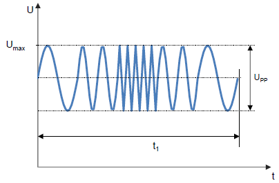
 6.E-06 Superimposed AC Voltage. Simulates AC voltage superimposed on the DC electrical system, a disturbance that may occur at any time during engine operation, evaluating the component’s tolerance to AC ripple interference.
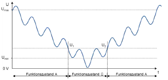
 7.E-07 Slow Supply Voltage Fall and Rise. Simulates gradual variation of the supply voltage during slow battery discharge and charging, evaluating the component’s functional adaptability and stability under slowly varying voltage.
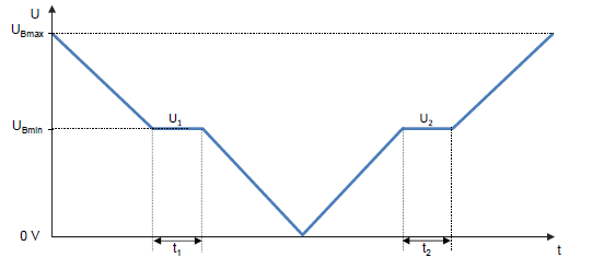 8.E-08 Slow Supply Voltage Fall with Fast Rise. Simulates the battery voltage slowly falling to 0 V and then suddenly reapplying the battery voltage, evaluating the component’s start-up and protection capability during voltage step recovery.
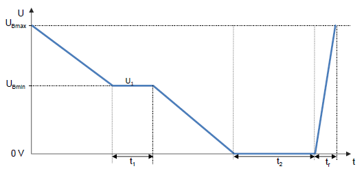 9.E-09 Reset Behaviour. Simulates the controller entering a reset state after recovery from a supply abnormality, evaluating the component’s reset logic, reset time and functional recovery after reset.
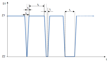
 10.E-10 Short Interruption. Simulates brief disconnection of the vehicle power supply (classified by interruption duration), evaluating the component’s function retention, data storage and recovery capability during momentary power loss.
 11.E-11 Cranking Pulse. Simulates the characteristic waveform in which battery voltage drops sharply to a low value and then rises slightly at engine start-up, and also covers repeated cranking after the engine has started, evaluating the component’s immunity to low-voltage dips.
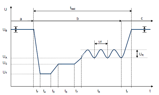
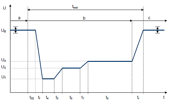 12.E-12 Voltage Ripple with Intelligent Generator Regulation. Simulates the ripple waveform produced during voltage regulation by an electrical system equipped with an intelligent generator voltage regulator, evaluating the component’s adaptability to slowly varying voltage ripple.
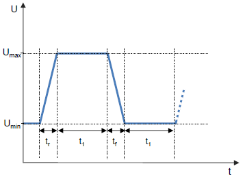 13.E-13 Pin Interruption. Simulates an open-circuit fault on an individual pin, evaluating the component’s ability to diagnose pin open circuits and degrade into a defined fault state.
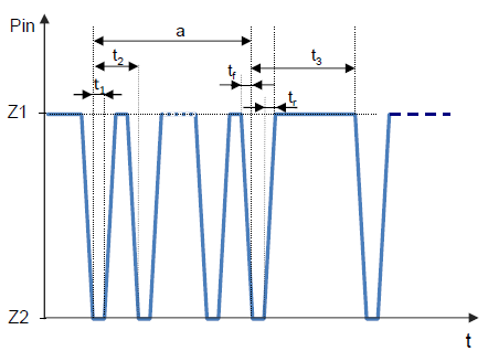 14.E-14 Connector Interruption. Simulates an open-circuit fault in connector wiring, evaluating the component’s functional behaviour and safety protection capability under connector open-circuit conditions.
15.E-15 Polarity Reversal. Simulates reverse-polarity battery connection during start-up, evaluating the withstand capability and protection behaviour of the component under test (DUT) against reversed polarity.
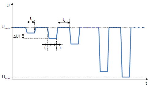
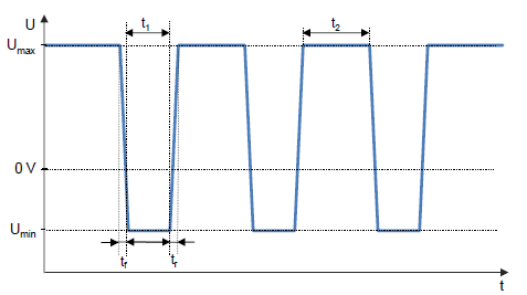 16.E-16 Ground Offset. Simulates conditions in which a potential difference exists between different ground locations. Potential differences between ground points may cause signal distortion between connected components; the requirement is that a potential difference of ±1 V (static) between ground points in an electrical assembly does not affect component function.
17.E-17 Short Circuit in Signal and Load Circuits. Simulates short-circuit faults at equipment inputs, outputs and load circuits, evaluating the component’s short-circuit withstand capability and the effectiveness of its built-in protection circuitry. 18.E-18 Insulation Resistance. Determines the insulation resistance between insulating isolated elements, verifying the effectiveness and safety of the insulation isolation design under humid and heat conditions. 19.E-19 Quiescent Current. Determines the current consumption of the component in its static (sleep) state, evaluating static power performance and its impact on overall vehicle standby energy consumption. 20.E-20 Dielectric Strength. Simulates the dielectric strength limit condition between internal insulating parts of the component, verifying the withstand voltage capability of the insulating material. 21.E-21 Feedback. Verifies that no feedback exists from the component under test (DUT) to the switch terminals (T.15, T.77), evaluating the independence and crosstalk immunity of switch signal channels. 22.E-22 Overcurrent. Determines the overcurrent withstand strength of mechanical switches, electronic outputs and contacts, verifying their reliability and service life margin under overload conditions.
4. Impact of Test Non-Conformity on Vehicle Safety
A failure in electrical performance testing means that the component’s withstand capability or functional stability under a specific abnormal electrical condition does not meet the standard requirement. Such defects often appear only as intermittent anomalies during development, but once the component is fitted to series-produced vehicles they may develop into the following safety events:
Engine stall and loss of propulsion while driving. When cranking pulse (E-11) or transient undervoltage (E-03) fails, the controller may reset or hang at the moment of voltage dip, causing the engine to stall and the vehicle to lose propulsion abruptly while driving.
Malfunction and loss of control of common vehicle functions. Failure of superimposed AC voltage (E-06) or slow supply voltage fall and rise (E-07/E-08) readily causes flickering, failure or unintended operation of the instrument cluster, lighting, wipers and window systems.
Degradation or failure of safety-related systems. If electronic parts closely related to safety, such as EPS, ESC and ADAS, fail under voltage disturbance, steering and braking assist capability is directly impaired, accompanied by warning lamp illumination and degradation to limp mode.
Over-stress damage of devices and latent batch early failures. Failure of items such as sustained overvoltage (E-01), Load Dump (E-05) and short circuit (E-17) causes over-stress damage to power ICs, power devices and connector contacts inside the ECU, creating latent batch early-life failures.
After-sales claims, defect investigations and recalls. When such defects surface during customer use, they directly trigger warranty claims, market complaints and even defect product recalls. The manufacturer must bear recall remediation costs, compensation and reputational damage. Public cases already exist in China of entire vehicle recalls caused by electronic component damage resulting in engine stall while driving.
5. Typical Failure Modes and Improvement Recommendations
Based on common failure mechanisms, systematic remediation is recommended across five areas: hardware selection, circuit architecture, software strategy, manufacturing process and verification process:
Input-stage protection. Configure TVS diodes, varistors, common-mode inductors and filter capacitors at the power input to build a first line of defence. TVS selection must be verified against the actual maximum continuous working voltage and surge energy, avoiding premature breakdown or insufficient energy absorption caused by selecting only by nominal peak voltage.
Power supply architecture optimisation. Allocate LDO and DC-DC power hierarchy rationally, minimise supply path impedance and avoid common-impedance coupling between high-current loops and signal loops. Select wide input voltage range devices and reserve sufficient voltage margin so that undervoltage dips and overvoltage surges do not enter the failure region.
Software and control strategy. Set reasonable undervoltage/overvoltage monitoring thresholds, configure an independent watchdog and fault self-recovery mechanism, and define function degradation strategies under voltage dip so that critical functions are retained first while secondary functions exit in an orderly manner.
Grounding and signal isolation. Optimise the ground layout and unify the reference ground, ensuring the potential difference between ground points meets the ±1 V (static) requirement. Increase physical spacing and routing separation between signal lines and load lines to reduce crosstalk.
Connector and harness workmanship. Select connectors that meet current-carrying capacity and mating life requirements, control terminal plating quality and crimp height, and add redundancy for critical pins to eliminate functional failures caused by pin or connector interruption (E-13/E-14).
Front-load verification. Move the full VW 80000 test programme forward into the design validation (DV) and pre-production (PPAP) phases, driving it forward as a closed loop of “baseline testing — root-cause analysis — design remediation — retest verification” so that defects do not flow into series production and after-sales.
6. One-Stop Testing and Remediation Service
We provide a full closed-loop service covering testing, analysis, remediation and retest, helping customers complete VW 80000 conformity verification in the shortest possible cycle:
Standard-compliant testing. Execute the full E-01 through E-22 test programme in accordance with VW 80000, GB/T 28046.2 and ISO 16750-2, using dedicated equipment including ripple generators, power supply voltage variation simulators and microsecond switches, with full data recording and waveform capture throughout.
Customised matching. Match test groups, severity levels and acceptance criteria to the product’s mounting location (engine compartment / passenger compartment / exterior), supply system type (12 V / 24 V) and the customer’s own corporate standards, avoiding ineffective testing.
Failure localisation. Conduct failure analysis (FA) on non-conforming items, localising the root cause to a specific circuit element — protection device selection, PCB layout, power supply chain, software strategy or connector workmanship — and delivering a clear, traceable root-cause conclusion.
Remediation support. Provide actionable design recommendations and alternative component selections based on the root cause, and work closely with the customer through verification retesting of revised samples until the standard acceptance criteria are met.
Report delivery. Issue bilingual test reports compliant with CNAS and CMA accreditation requirements, fully covering test data, waveform curves, acceptance basis and before/after remediation comparisons, ready for direct use in customer OEM sample submission and series-production release.
7. Principal Test Equipment
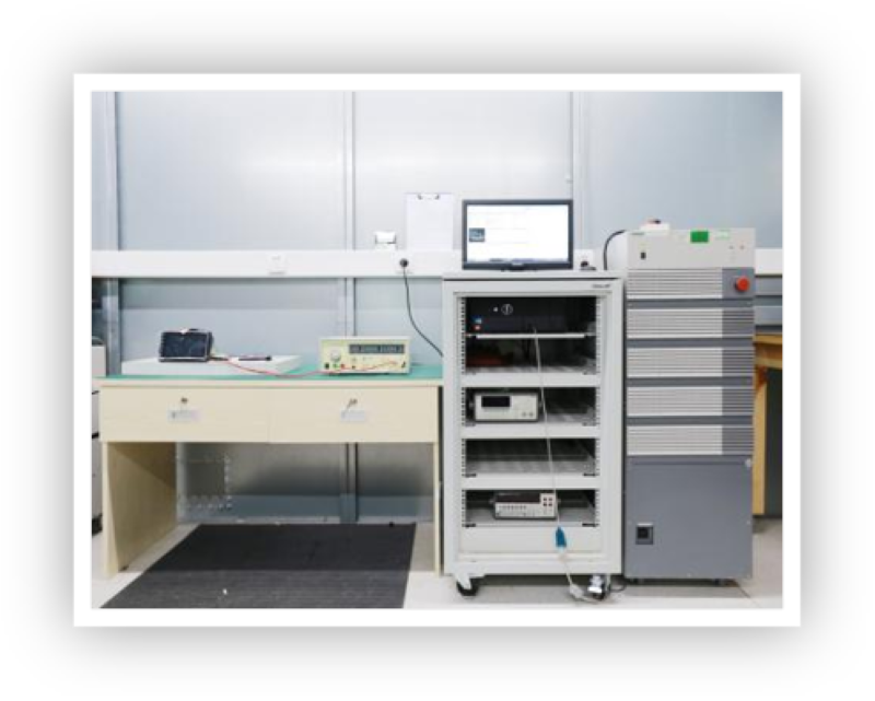
VW 80000 electrical performance testing relies on dedicated waveform generation and voltage regulation equipment. A typical configuration is as follows:
Ripple Generator / Power Supply Voltage Variation Simulator
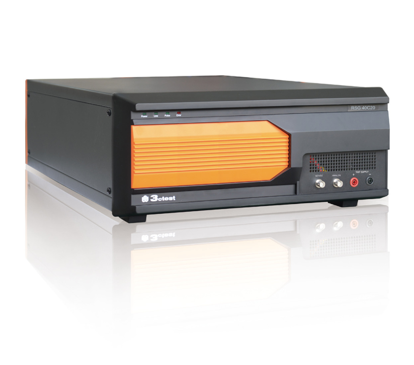 Ripple Generator
 Microsecond Switch
 VW 80000 evolved from LV 124 and is now the accepted electrical performance entry requirement for the German vehicle supply chain. Passing the Chinese national standard does not automatically satisfy German OEM requirements; suppliers must execute each standard separately as specified by the customer. Mastering the tests, pinpointing root causes, completing remediation and closing the loop through retesting is essential for component manufacturers to improve reliability and avoid series-production and after-sales risk. We provide one-stop service from baseline testing through verification retest — please contact us for details.